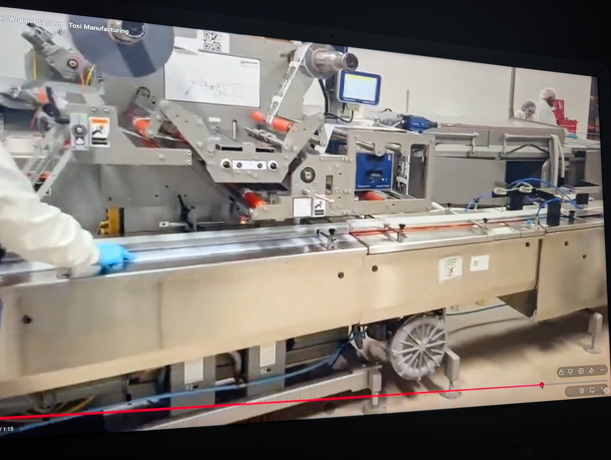
Campbell Revolution Wrapper
CAMPBELL REVOLUTION 5 AXIS WRAPPER WITH DISTRIBUTION SYSTEM
Year: 2023
This order is organized into the following components:
I. Product Distribution System
Il. Revolution Five Axis Servo Horizontal Wrapping Machine & Light
Contact Feeder
Model:
Revolution
Category:
Wrappers
Availability:
Available
Description
REVOLUTION FIVE AXIS SERVO HORIZONTAL
WRAPPING MACHINE & LIGHT CONTACT FEEDER:
1.1 Product Specifications
Description
1. Simple Bar. Size 4.125" × 1.00" × 0.75". PER MINUTE 300-450
2. Trim Healthy Bar. 4.00" × 1.75" × 0.50". PER MINUTE 200-250
3. Enrobed bar 4.00" × 2.00" × 0.63" PER MINUTE 200-250
4. Rice Crispie Bar. 4.00" × 1.75" × 0.63". PER MINUTE 200-250
1.2 Type of Wrapping Material
1.2.1 Cold & Heat Seal Film
1.3 Type of Wrap
1.3.1 Fin Seal, Crimped Extended Ends
1.4 Wrapper Performance
1.4.1 Wrapping machine performance estimates are dependent upon film sealability and product feeding capabilities. Wrapping systems will accept and wrap products at a rated speed of up to 450 products per minute per leg if properly delivered by the distribution system.
Section 2: General
2.1 Standard Features
2.1.1 One (1) left hand machine configured with the product flowing from right to left as the
operator faces the control panel.
2.1.2 Utility specs: Electrical-480 volt, 3 phase, 60 Hz. Air-80 PSIG.
2.1.3 Gray powder coated exterior and stainless steel guards.
2.1.4 Category 3 safety circuit wiring.
2.1.5 Standard safety features including light stack, guarding, guard safety switches, E-stop button with E-stop relay and machine reset button, safety cable stop on infeed conveyor and lockable main power disconnect.
Section 4: Feeder
4.1 Standard Features
4.1.1 Product Transport Conveyors
4.1.1.1 Flat belt conveyors and 90 degree curve conveyor
4.1.1.2 Product transport conveyors will be driven by AC motors controlled by variable speed control.
4.1.1.3 Small diameter nose rollers
4.1.2 Two Belt Gap Altering Section
4.1.2.1 Belt sections controlled to accept product and to alter gaps prior to turning unit
4.1.2.2 Top and bottom belt product conveyance
4.1.2.3 Small diameter nose and tail rollers for smooth product transfer
4.1.3 Product Turning Conveyor
4.1.3.1 Servo driven split belts and side belt turning system
4.1.3.2 Small diameter nose and tail rollers for smooth product transfer
4.1.3.3 Independent motor for the side belt that can be saved into recipe for product and speed related changes
4.1.4 Product Reject Station (located on bar turning section)
4.1.4.1 Photo-eyes, brackets, air solenoids, air nozzles and all necessary programming for connected, short and unturned bars
4.1.5 Metal Detector conveyor with air blast reject station.
4.1.6 Moving Junction Feeder
4.1.6.1 Servo driven gap closing belt
4.1.6.2 Servo driven locating belt
4.1.6.3 Servo driven moving junction carriage between belts
4.1.6.4 Moving junction carriage position automatically adjusts length of belt conveyors dependent on product supply and controlled to close gaps between rows of product and backlog product with extremely light contact
4.1.6.5 12'-0" overall length, 8'-0" of moving junction travel
4.1.6.6 Wrapper speed based upon product backlog with settings for upper and lower wrapper speed limits.
4.1.6.7 Automatic belt tracking
4.1.6.8 Pneumatic belt tensioning
4.1.6.9 Belt width of 6.0"
4.1.7 Locating Belt
4.1.7.1 Bottom belt with vacuum assist jump driven from the moving junction's locating belt
4.1.7.2 Photoelectric scanners for product sensing
4.1.7.3 Small diameter nose and tail rollers for smooth transfer of product
4.1.8 Two (2) Phasing Belts
4.1.8.1 Servo-driven bottom belt with vacuum assist
4.1.8.2 Photo-electric scanners for product sensing with stainless steel brackets.
4.1.8.3 Small diameter nose and tail rollers for smooth transfer of product
4.1.9 Split Belt Conveyor
4.1.9.1 Split belt transfer conveyor transfers the individual products into the wrapper infeed flights. Split belt conveyor to be driven off the infeed conveyor.
4.2
Additional Features
4.2.1 Powder coated steel construction and stainless steel and FDA approved materials for product contact parts.
4.2.2 Guarding on operator side of feeder and infeed conveyor to be hinged and fold-down style
4.2.3 Hoffman painted wireway located on drive side of feeders, mounted on a 45 degree angle
4.2.4 Laser etched threading diagrams for the feeder belts on the inside of the drop down guards.
Section 5: Infeed
5.1 Standard Features
5.1.1 Easy clean infeed conveyor. Construction consists of stainless steel, hard coat anodized aluminum and FDA approved materials. Infeed conveyor to include hinged top plates and drop down style side covers providing easy access for cleaning and sanitation. All parts in contact with the product are of stainless steel or FDA-approved material including stainless steel sprockets and shafts.
5.1.1.1 Stainless steel conveyor deck
5.1.1.2 Appropriate side guides
5.1.2 Electronic torque sensing for infeed chain drive protection.
5.2 Additional Features
5.2.1 UHMW covered top plates
5.2.2 High product detector will stop machine when a product exceeding height specifications is detected.
5.3 Change Parts
5.3.1 One (1) Infeed chain; standard chain with stainless steel lugs
Section 6: Backstand and Feedroll
6.1 Standard Features
6.1.1 Dual roll cantilevered backstand with air operated core lock and independent screw adjustment for roll centering accommodates quick roll changes. Dancer arm and brake system provides consistent film tension throughout roll diameter changes and prevents film overrun during stops.
6.1.1.1 Maximum roll width 16 inches; maximum roll diameter 16 inches; 3 inch diameter cores.
6.1.2 Servo controlled powered feed roll system provides consistent film speed control. Features quick release nip roll arrangement for easy film threading.
6.1.3 Automatic verification that nip roll is closed; machine will not run with nip roll in open position.
6.2
Additional Features
6.2.1 Slack web detector monitors film tension and will automatically stop the wrapper in the event of a film break.
6.2.2 Servo controlled registration system provides precise film print positioning.
6.2.3 Automatic web splicer will splice registered or unregistered film in running mode.
6.2.4 Urethane film guide rolls as required for cold seal film.
6.2.5 Campbell Wrapper supplied thermal transfer printer including mounting brackets and installation.
6.2.5.1 VideoJet 6530 Thermal Transfer Printer
6.2.5.2 120VAC power receptacle supplied for printer
6.2.5.3 PLS signal provided for printer timing
6.2.5.4 Printer fault output wired to position stop machine
Section 7: Tubing
7.1 Standard Features
7.1.1 Three (3) sets of fin wheels are used to make the longitudinal seal. A servo drive to the 1st set of fin wheels and separate servo drive to the 2nd and 3rd sets of fin wheels provides the ability to "trim" fin wheel speed for optimal film tension control. All fin wheel assemblies are easily cantable on the fly from above the deck plate for better control of
package tightness. Manual release of 1st fin wheels keep film positioned during stops and automatic release of 2nd and 3d sets of fin wheels prevents film from burning during machine stops.
7.1.1.1 One (1) set of cold fin wheels
7.1.1.2 Two (2) sets of hot fin wheels
7.1.2 Heaters are mounted in fin wheels. Brushless sealed contacts are used to transfer heater power and thermocouple signals.
7.2 Change Parts
7.2.1 Three (3) Adjustable height and fixed width formers
7.2.2 Three (3) Sets of knurled fin wheels
Section 8: Cutting Head
8.1 Standard Features
8.1.1 Servo-driven cutting head assembly.
8.1.1.1 Two-up cutting head.
8.1.2 Heaters are mounted in crimpers providing a uniform temperature pattern. Brushless sealed contacts are used to transfer power and thermocouple signals.
8.1.3 Servo drive to cutting head adjusts crimper speed to match film speed and is easily adjusted via PanelView entry when changing product lengths.
8.1.4 Automatic position stop with crimpers in open position prevents film from burning.
8.1.5 Electronic torque sensing for cutting head drive protection.
8.2 Additional Features
8.2.1 Mount terminal blocks on cutting head shafts for easy crimper removal.
8.3 Change Parts
8.3.1 Two (2) Sets of horizontal lined crimpers (set consists of 1 upper and 1 lower crimper)
8.3.2 Two (2) Zig-zag knives
8.3.3 One (1) Cutting head product support
Section 9: Discharge Conveyor
9.1 Standard Features
9.1.1 Straight-out belt discharge conveyor
9.1.1.1 Extends 24 inches beyond frame.
9.2 Additional Features
9.2.1 Reject system including air solenoid, dual air nozzles, extended discharge conveyor, programming, set-up and test at Campbell Wrapper Corporation.
Product to be rejected to operator side of conveyor. Rejects for the following conditions:
9.2.1.1 Spliced packages
9.2.1.2 Film manufacture splice (splice tape to be of a solid dark color, red preferred)
9.2.1.3 Connected packages
9.2.1.4 Film out of register packages
9.2.1.5 After extended stop
9.2.1.6 Start-up packages
9.2.1.7 Short product
9.2.2 Driven hold-down wheel mounted on the discharge conveyor.
Section 10: Electrical
10.1 Standard Features
10.1.1 Allen-Bradley drive and control package to be provided including:
10.1.1.1 PanelView Plus 7 1000 color touchscreen operator interface with built-in PDF viewer and Ethernet communications
10.1.1.2 ControlLogix 5000 Series PLC control
10.1.1.3 AB Kinetix 5700 servo amplifiers with Ethernet communication
10.1.1.4 AB VPL servo motors
10.1.1.5 Menu-driven set-up procedure
10.1.1.6 Two level access, one secured, one unsecured
10.1.1.7 Product per minute display, totalizer display, production records and fault display included
10.1.1.8 Forty (40) record set-up storage recipe retrieval
10.1.1.9CE / UL touchsate components
10.1.1.10 Quick disconnect sensors and actuators
10.1.1.11 Campbell "No Homing" feature for most E-stop and guard opening conditions
10.1.2 Pedestal mounted electrical control station with adjustable position for easy access by machine operator.
10.1.3 Internal control of four temperatures with access through PanelView for control of each heated fin sealer assembly, upper crimper shaft and lower crimper shaft.
10.1.4 Delayed start with audible alarm provides notice that machine will be starting.
10.1.5 Stainless steel electrical cabinet doors and operator control station.
10.2 Additional Features
10.2.1 Allen-Bradley ENT Ethernet card for plant network communication.
10.2.2 Graceport with Ethernet port and 120 VAC GFCI mounted in the main electrical enclosure door.